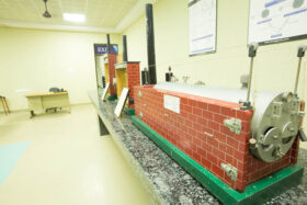
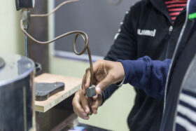
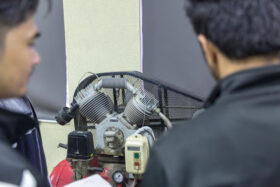
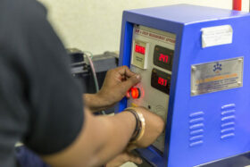
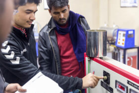
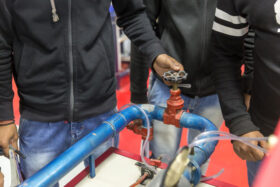
This lab is equipped with advanced equipment like propeller, watt, potter & Hartnell governer, motorized gyroscope, balancing apparatus. In this lab, the students prepare performance characteristic curves and study of the stability, sensitivity, and balancing of reciprocating and rotating masses.
- To perform an experiment on Watt and Porter Governors to prepare performance characteristic Curves, and to find stability & sensitivity.
- To perform an experiment on Proell Governor to prepare performance characteristic curves, and to find stability & sensitivity.
- To perform an experiment on Hartnell Governor to prepare performance characteristic Curves, and to find stability & sensitivity.
- To study gyroscopic effects through models.
- To determine gyroscopic couple on Motorized Gyroscope.
- To perform the experiment for static balancing on the static balancing machine.
- To perform the experiment for dynamic balancing on the dynamic balancing machine.
- Determine the moment of inertial of connecting rod by compound pendulum method and tri-flair suspension pendulum.
Universal Governor Apparatus & Tachometer- The function of the governor is to maintain the speed of an engine within specific limit whenever there is a variation of load. The governor should have its mechanism working in such a way, that the supply of fuel is automatically regulated according to the load requirement for maintaining approximately a constant speed. This is achieved by the principle of centrifugal force. The centrifugal type governors are based on the balancing of centrifugal force on the rotating balls by an equal and opposite radial force, known as the controlling force.
Governors are broadly classified as:
- a) Centrifugal Governors.
- b) Inertia Governors.
Models of Aeroplane and ship-The earliest observation and studies on gyroscopic phenomenon carried out during Newton‟s time. These were made in the context of the motion of our planet which in effect in a massive gyroscopic. The credit of the mathematical foundation of the principles of gyroscopic motion goes to Euler who derived at set of dynamic equation relating applied mechanics and moment inertia, angular acceleration and angular velocity in many machines, the rotary components are forced to turn about their axis other than their own axis of rotation and gyroscopic effects are thus set up. The gyroscopes are used in ships to minimize the rolling & pitching effects of water.
Gyroscopic couple on Motorized Gyroscope-When a body moves along a curved path with a uniform linear velocity, a force in the direction of centripetal acceleration (known as centripetal force) has to be applied externally over the body so that it moves along the required curved path. This external force applied is known as active force. When a body, itself, is moving with uniform linear velocity along a circular path, it is subjected to the centrifugal force radially outwards. This centrifugal force is called reactive force.
Balancing of rotating parts and find the unbalanced couple and forces-If a shaft carries a number of unbalanced masses such that center of mass of the system lies on the axis of rotation, the system is said to statically balance. The resultant couple due to all the inertia forces during rotation must be zero. These two conditions together will give complete dynamic balancing. It is obvious that a dynamically -balanced system is also statically balanced, but the statically balanced system is not dynamically balanced.
Pendulum method and tri-filar suspension pendulum-
Compound Pendulum: – When a rigid body is suspended vertically, and it oscillates with a small amplitude under the action of the force of gravity, the body is known as a compound pendulum.
Trifilar Suspension (Torsional Pendulum):- It is also used to find the moment of inertia of a body experimentally. The body (say a disc or flywheel) whose moment of inertia is to be determined is suspended by three long flexible wires A, B, and C, as shown in fig.-b. When the body is twisted about its axis through a small angle θ and then released, it will oscillate with simple harmonic motion.
Various types of the dynamometers-The dynamometer is a device used to measure the torque being exerted along a rotating shaft so as to determine the shaft power.
Dynamometers are generally classified into:
1) Absorption dynamometers (i.e. Prony brakes, hydraulic or fluid friction brakes, fan brake and eddy current dynamometers)
2) Transmission dynamometers (i.e. Torsion and belt dynamometers, and strain gauge dynamometer)
3) Driving dynamometers (i.e. Electric cradled dynamometer)
Prony Brake: The prony and the rope brakes are the two types of mechanical brakes chiefly employed for power measurement. The prony brake has two common arrangements in the block type and the band type. Block type is employed to high-speed shaft and band type measures the power of low-speed shaft.
Block Type Prony Brake Dynamometer:– The block type prony brake consists of two blocks of wood of which embraces rather less than one half of the pulley rim. One block carries a lever arm to the end of which a pull can be applied by means of a dead weight or spring balance. A second arm projects from the block in the opposite direction and carries a counterweight to balance the brake when unloaded. When operating, friction between the blocks and the pulley tends to rotate the blocks in the direction of the rotation of the shaft. This tendency is prevented by adding weights at the extremity of the lever arm so that it remains horizontal in a position of equilibrium.

